|
[Next page is an image: Instruments used in Magnetic Observations]
450 FIRST REPORT UPON MAGNETIC WORK
MAGNETIC INSTRUMENTS.
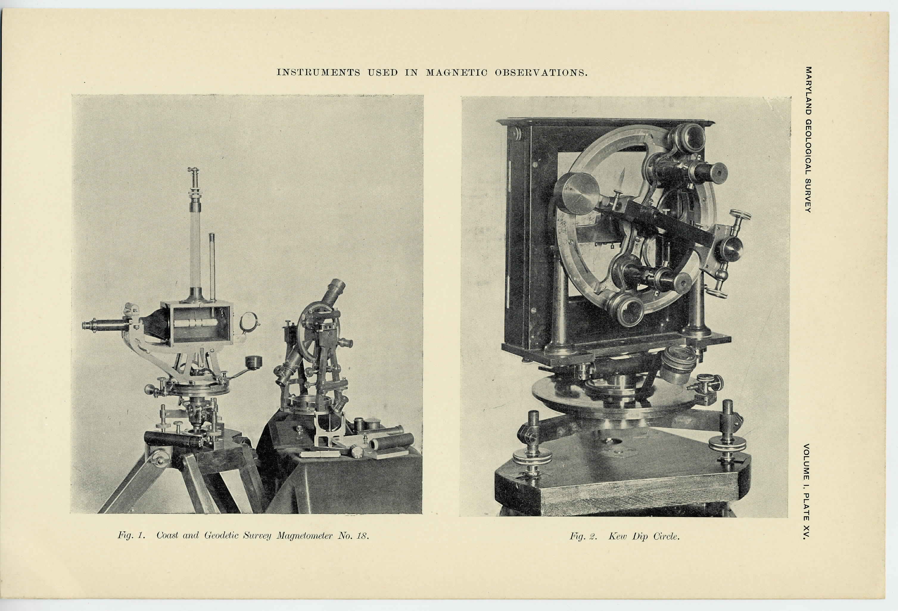
The instrument used to determine the magnetic decimation and the
intensity of the earth's magnetic force is shown in Plate XV, Fig. 1.
It is a combination magnetometer and theodolite, being one of the four
new instruments constructed at the Coast and Geodetic Survey office in
1893 and known as No. 18. In its general form the instrument is
similar to those that have been in use in the Coast and Geodetic
Survey for some years, an illustration of the earlier form being given
in the Survey Report for 1881, Appendix No. 8, plate 36. The new
instruments are a little larger than the old ones and are improvements
upon them in details of design, and especially in stability and perfec-
tion of workmanship.
The magnetometer proper, ready for determining the magnetic de-
clination, is shown in the left of the figure. The magnet, octagonal
in shape, is a hollow steel bar about three inches long and nearly one-
half inch thick. This takes the place of the magnetic needle in the
ordinary surveyor's compass. Instead of swinging about on a pivot-
point it is suspended by one or two fine silk fibres, and the friction is
thus practically eliminated. These fibres are hung in the glass tube
projecting above the box in which the magnet is enclosed; one side
of this box is removed, so as to permit seeing the magnet. The fibres
are tied at the lower end to a copper stirrup likewise octagonal in
shape, so that the magnet can easily be slipped inside the stirrup
and rest there securely. When the little pin at the bottom of the
stirrup fits in the small groove cut in the magnet, the latter is in
position. The fibres are fastened at the upper end to an adjustable
torsion head, permitting the fibres to be raised or lowered until the
magnet is at the proper height in the box. For the removal of the
torsion in the fibres a copper bar of the same weight and shape as the
magnet is provided and suspended in place of the magnet in the air-
tight box. The small amount of torsion left after the copper bar
comes to rest can be quickly removed by properly turning the torsion-
head on top and thus the plane of no torsion be made coincident with
the plane through the magnetic meridian. By this arrangement all
error to be ascribed to friction of the compass needle on the pivot is
|
 |